RC BAJA: STEERING AND SUSPENSION
ANALYSIS
During Winter quarter, analyses were conducted on the suspension and steering of the RC Baja, the majority of components that experience forces are the suspension components and the tie rods of the steering components. Analyses are conducted on these components to understand if the materials and design are capable of passing the tests without breaking and completing the listed requirements. The first analysis in Figure A1, is done under requirement of a drop test. Assuring that the RC does not break, the analysis confirms the RC will withstand the impact of dropping from 2.13ft. The second analysis consist of figuring out the k factor of the spring. The requirement relation to this analysis is that the suspension travel is to be only 0.1". See Figure A02. Under those conditions, the spring factor is calculated to be 30617(lbm/s^2) and the force reaction to be 951lbf on all 4 wheels from a drop of 2.13ft. The Shock tower analysis in Figure A3&A4 are done to figure out how much force will be exerted on the crossmember and if it will deflect more than 0.1". An analysis on the bolt size will allow mounting to the chassis. See figure A5. Assuming 5lbf shear and single shear the calculations revealed a standard 4mm is suitable.
Requirements
-
Wheels turn 60 degrees without interference.
-
RC Baja must be able to have 1.5” of clearance for suspension.
-
Must have suspension travel of 1”.
-
RC should not exceed 10lbs.
-
RC uses M3 and M4 standard fittings.
-
RC should not deflect more than 0.1” at a 2ft drop test more than once.
-
The RC can go 30 mph max.
-
Can withstand an impact at 30 mph.
-
Components must not deflect more than 0.1”.
-
Suspension must support 10 lbs.
-
Must have less than 4-foot turning radius.
-
E6000 Adhesive will not fail from a 2ft drop.
Analysis 1
This analysis is related to the requirement of weighing less than 10lbs and will be dropped from a 2.13ft height. The calculations are based on assuming the RC exerts 5lbf of weight. The analysis demonstrated the force reaction on the spring and the rest of the control arm. The reactions being 95.85lbf at 45 degrees from horizontal at point B and -99.72 at point C. See Figure A01 below.

Figure A01- Analysis of force acting on the wheel from a 2.13ft and the reaction forces of that load on the shock lower mount location.
Analysis 2
This analysis was done to find the suspension k factor and force required to compress the spring 1" from its equilibrium. This analysis utilizes information already found from analysis 1. By setting mgh=.5fx^2 and setting the givens in place, the k factor, was calculated to be 30617(lbm/s^2). Next, each spring is to experience 237.75lbf when dropped from 2.13ft. See figure A02 below.

Figure A02- Analysis of suspension travel and required k factor of a 4” spring that does not compress more than 1”.
Analysis 3
The analysis in Figure A3 is on the shock tower. Assuming the crossmember to be a beam, a random value for the cross section width was selected and used for calculating a height value using bending stress equation to then verify if it will be allowable bending stress and find deflection. The minimum width for the cross section under the yield stress is .46in. Knowing that, b was chosen to be .75in. A deflection calculation is done with the new width and it shows it will deflect 0.02966in. This value being less than our required 0.1" fits well. Next a bending stress calculation is done to compare to the max stress value. See Figures A03.1 and .2 below.
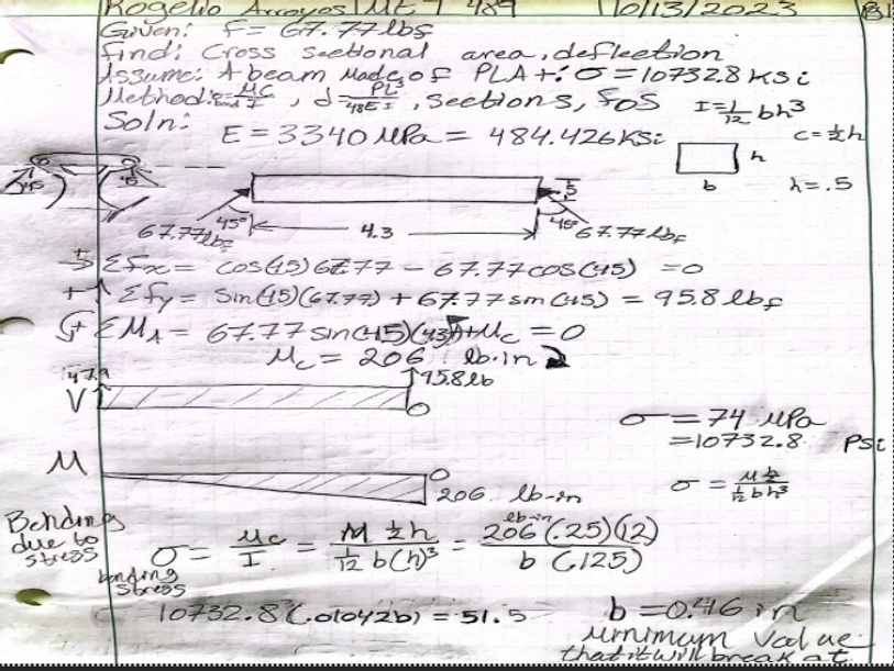
Figure A03.1- This analysis is done to find the width of the sectioned portion of the shock tower.
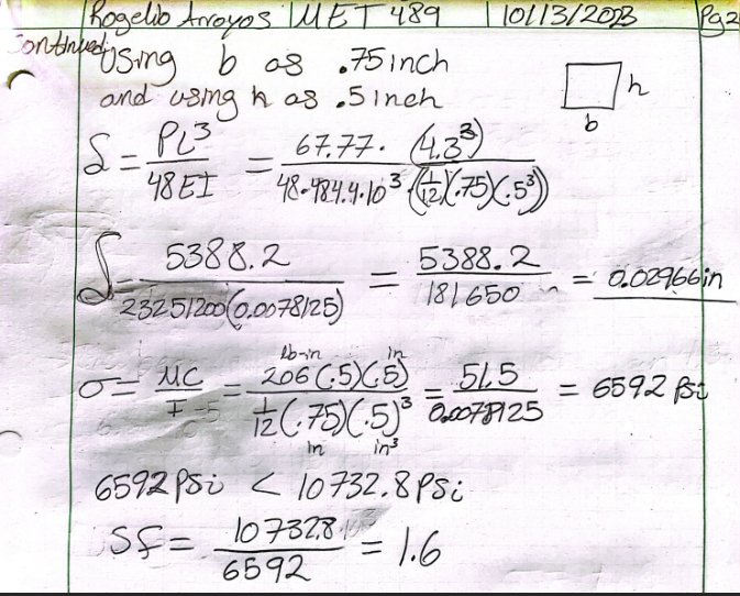
Figure A03.2- continued.
Analysis 4
In this analysis, the problem was to find the correct hardware size that is closest to standard that’ll hold the shock tower in place. Thus, the shear force equation is applied to find the diameter of the hole. Assuming to be a steel bolt with a yield stress of 36ksi and a shear force of 5lb, it was determined the minimum diameter for the bolt to shear under 5lb load is 0.0133in. A M4 standard bolt will be used in place for availability and budget reasons. See Figure A04 below.

Figure A04- Analysis done on figuring out what the bolt size should be to hold the shock tower to the chassis.
Analysis 5
This analysis is related to the requirement of a 4-foot turning radius and allowing for 60 degrees of angle without interference (req. 1d-1 & 1d-11). Utilizing the dimensions of the track width and the wheelbase, the steering angle is calculated using an arctangent equation and setting the respective values in place. The result of this being 71.6 degrees. Using the steering angle estimation, the turning radius is calculated by subtracting 71.6 and 90 from 180 to get the unknown angle of 18.4 degrees. Then using the tangent formula, the length of the turning radius is 30” inches. See Figure A05 below.

Figure A05- Analysis of the steering angle of the RC and as well as the turning radius.
Analysis 6
The problem in this analysis is the deflection and stress requirement needed for the drop test (Req. 1d-6). The analysis began with a guess for the cross section to see if it would withstand the force applied without exceeding 0.1” of deflection. Results revealed it would have deflected 0.64”. Nest, bending stress was calculated, but the value exceeded the max yield stress on the PLA+ material under those dimensions. A new cross section was calculated by setting the base of the cross section to be 0.3” in the bending stress equation. This produced a 0.5” height value that was verified to deflect only 0.06” and bending stress less than the max yield stress for the material. See figure A06.1 and .2 below

Figure A06.1- Analysis of the lower control arm assuming it to be a solid beam.
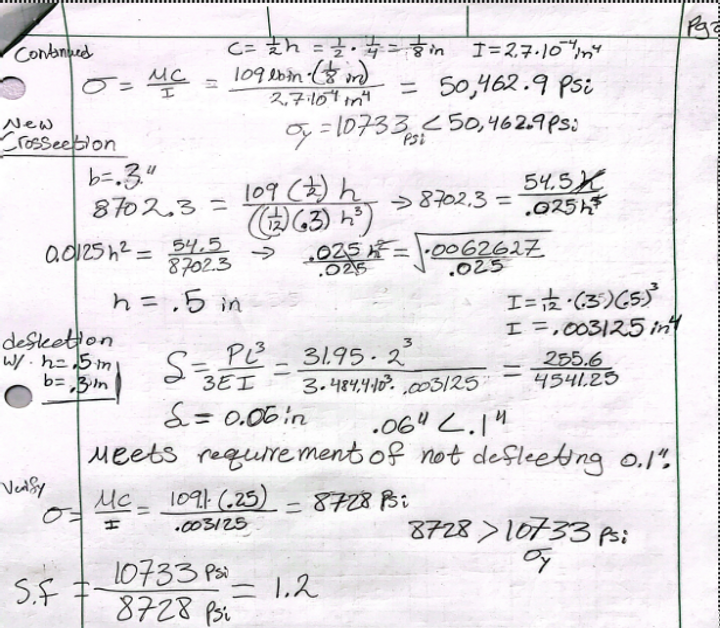
Figure A06.2- Continuation of Figure A06.1.
Analysis 7
The problem in this analysis is the deflection and stress requirement needed for the drop test (Req. 1d-6). The analysis began with a cross section of 1x0.75in to see if it would withstand the force applied without exceeding 0.1” of deflection or yielding. Results revealed the first arm would have deflected 0.0077” and experienced 919.84psi, well under the yield stress of 10733psi. The deflection showed it was well under the required deflection of 0.1”, as listed under 1d-6. Next the second arm had a cross section of 1x0.98in. Results showed the arm would deflect 0.00356” and have 538.7psi acting on it. Both arms are to be experiencing less than the required maximum deflection and should not surpass the yield point according to the material properties. See Figure A07.1 and A07.2 below.
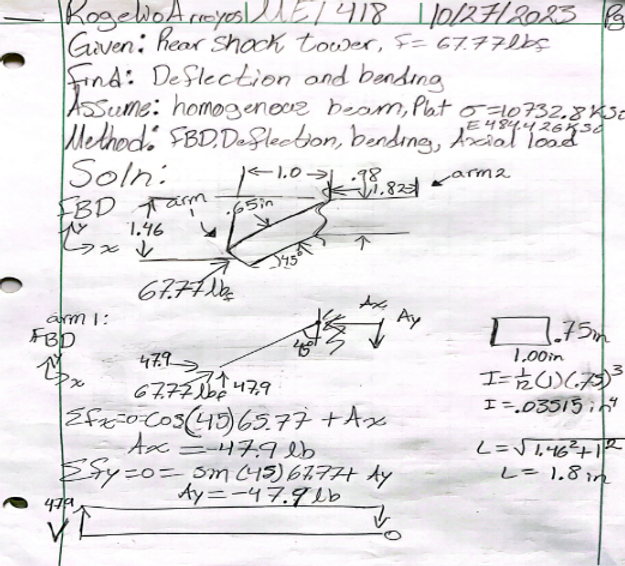
Figure A07.1- Rear tower shock analysis.
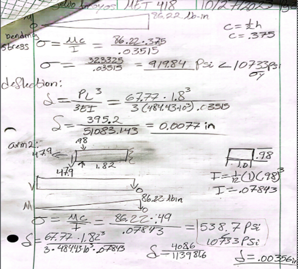
Figure A07.2- Continuation of Figure A07.1.
Analysis 8
The problem in this analysis is the torque applied on the steering pin on the steering rod (Req. 1d-1). The analysis is done assuming the “mu” factor is 0.5 and the force of the RC car is 5lbf. The mass would then be 0.16lbm. Also, assuming the space between the center of the tire and pin is 1.7in. Finally, the tire width being 4.06in. According to the calculations the torque applied to the pin would be 0.18lb-in. The torque applied to the steering pin is assumed that nothing will be interfering with the actions because the RC must be able to turn its wheels at all times. See Figure A08 below.

Figure A08- Torque analysis on steering pin.
Analysis 9
This analysis begins with the force of the impact when the RC is going at its max speed of 30mph given as 4382.4lb. The requirement for the RC is that it must reach 30mph and withstand an impact at 30mph (req 1d-7, 1d-8). The control arm is assumed to have the material properties of PLA+ filament. The yield point of PLA+ is 10733ksi and the modulus of elasticity is 484.426ksi. Firstly, the reaction forces were calculated and the moment of the load about point A was found. The moment value was used to calculate a stress of 2.208ksi, much less than the yield point of 10733ksi. Changes to the cross section are not necessary with this analysis because the value of the bending stress is less than the max. The analysis shows that requirement 1d-8 is met, and the RC won’t deform because it will not surpass the max bending stress. See Figure A09 below for calculations.

Figure A09- Impact analysis based on force of the RC hitting a wall at full speed.
Analysis 10
The problem in this analysis is to find the bending stress of the lower control arm from a 2ft drop as required in 1d-6. In addition, the RC must not exceed 10lb (req. 1d-4). The part is to be printed out of PLA+ so that the Modulus of elasticity and yield point are given as 494.426ksi and 10733ksi. The impact force from the drop is given as 67.77lb. The reaction forces are calculated in sections and the max moments are graphed in the shear moment diagram. The moments are used to calculate the bending stress applied and are experiencing less than the max bending stress of 10733ksi. The first member experiences 12412.5psi and the second member experiences 1424.6psi. Also, shear stress was calculated as 173.8psi and 150.6psi. According to the analysis, the control arm should not deform from a 2ft drop (req 1d-6) because it will not reach the max bending stress of 10733ksi. See Figure A10.1 and A10.2 below.

Figure A10.1- Drop test analysis on the rear lower control arm.

Figure A10.2- Continued.
Analysis 11
The problem in this analysis is to find the deflection of the front upper control arm from a 2ft drop as required in 1d-8. The part is to be printed out of PLA+ so that the Modulus of elasticity and length are given as 484.4ksi and 3.95”. Also, it is to not exceed a deflection greater than 0.1”. The Impact force on the arm with the first set of cross section dimensions of .25” x 0.4” was deflecting 1.5”, assuming it acts directly on the member. Modifications to the dimensions of the cross section were made till an adequate dimension would not deflect more than 0.1”. According to the new dimension from the analysis, the lower control arm should only deflect up to 0.096”. Because it deflects less than the required 0.1” (Req 1d-8) that means the new cross section is 0.6” x 0.75”. See Figure A11 below.

Figure A11- Deflection analysis on front upper control arm based on a 2ft drop requirement.
Analysis 12
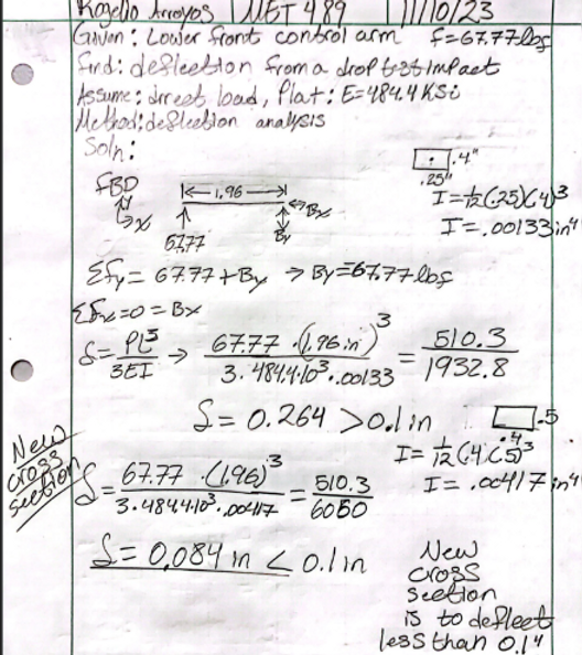
The problem in this analysis is to find the deflection of the front lower control arm from a 30mph impact as required in 1d-8. The part is to be printed out of PLA+ so that the Modulus of elasticity and length are given as 484.4ksi and 1.96”. Also, it is to not exceed a deflection greater than 0.1”. The Impact force on the arm with the first set of cross section dimensions of .25” x 0.4” was deflecting 0.264”, assuming it acts directly on the member. Modifications to the dimensions of the cross section were made till an adequate dimension would not deflect more than 0.1”. According to the new dimension from the analysis, the lower control arm should only deflect up to 0.084”. Because it deflects less than the required 0.1” (Req 1d-8) that means the new cross section is 0.4” x 0.5”. See Figure A12 below.