top of page
RC BAJA: STEERING AND SUSPENSION
CONSTRUCTION
The RC is mainly manufactured with 3d printed PLA+. This is an excellent choice of material for this project because parts can be easily assembled with others using threaded inserts and a soldering gun, superglue or friction itself. During the initial construction, the components were examined for improvements. The suspension was reconstructed and simplified. Nonetheless, the parts were still used for testing placement and alignment of components to their respective mounting place on the chassis. The manufacturer of the threaded inserts labeled the inserts to be 5.3in in diameter but really are closer to 5in in diameter. This had affected the construction of the RC because threaded inserts could not be added to fully assemble the RC. The shock tower sub assemblies were put together and notes were taken to try and improve the design around the purchased parts. The team discovered the RC was sitting too low. Experimenting with the parts, the lower control arms were swapped and flipped upside down. This raised the RC to 0.93in. Further attempt will be made to raise the RC for better clearance. In addition the use of washers and smaller fasteners are essential to minimize as much play in the suspension and steering. The RC was left at 1.5 inch clearance.

Figure C0- RC Car Assembly Tree.
![EMAD6870[1]](https://static.wixstatic.com/media/218d64_19e11607089a4692887a8b6ecd582c60f002.jpg/v1/fill/w_1470,h_797,enc_auto/file.jpeg)

All Videos
Video C0- Latest RC Front shock assembly with steering.
In the video above, it is demonstrating the 3d printed steering system working on the RC. The steering works as it should after tuning the transmitter to tell the servo what orientation the wheels must be to stay straight. The power to the servo can also be tuned for turning speed of the steering. The steering rods have been holding up as expected and could be redesigned further to allow for tighter turns if possible with the current design. The other half of the video shows the wiring setup to get the servo to be controlled remotely. The use of a more capable ESC helped the team eliminate the necessity to use a UBEC to power the servo motor. The LCA's changing meant the steering had to as well. The steering has undergone redesign to accommodate for the height change or else the rods would be experiencing torsional forces. To avoid changing the control arm ends slightly each time there had been a redesign, the control arms were designed to have ball joint ends for a range of motion and adjustments.
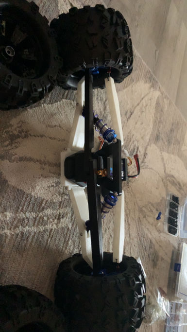
Figure C1- Partial construction of the front shock assembly with 2nd prototype lower control arms up front.
In Figure C1, the image shows a partial completed front shock assembly. The modeled and 3D printed components shown are the lower control arms (LCAs), the lower control arm mount, upper control arms (UCAs), and shock tower. In addition the two LCAs up front are the 2nd prototype to be tested. The first prototype would not allow for rotation of the knuckles to steer and so a new form of attaching with ball joint ends will be tested. Also, the UCA ends have been remodeled to fit hardware that will thread with ball joint ends. Assembly of the front shock section was straight forward. It would have been a wise choice to add inserts if the assembly was to be taken apart and assembled many times because with time, the plastic threads will wear out and threaded inserts will not.
![IMG_8290[1]_edited.jpg](https://static.wixstatic.com/media/218d64_82eff8dcdd1b4673bfe8440a1f7e6751~mv2.jpg/v1/fill/w_871,h_272,al_c,q_80,usm_0.66_1.00_0.01,enc_avif,quality_auto/IMG_8290%5B1%5D_edited.jpg)
Figure C1.1- Partial construction of the front shock assembly with latest prototype of front lower control arms.
In Figure C1.1 the latest prototype of lower control arms are shown. The new prototypes raise the chassis ground clearance to 1.75". The LCAS perform as expected and do not incorporate the ball joint ends like the rest of the connecting arms to the knuckles. This is because when the RC had the ball join ends on the lower control arms, the RC would deviate and not be rigid. So, 3d printed ball joint ends were used in place.

Figure C2- Front upper control arm modification.
In Figure C2, the upper control arms were redesigned to accept M3x16 bolts that would accept ball joint ends with M3 thread. The bolts were bonded to the ends of the control arms using JBWELD brand plastic bonder. This would prevent the bolt from moving when threading onto the bolt. The high strength structural adhesive required mixing before applying the adhesive and then allowed 15 minutes to cure. This was selected because it would work bonding plastic to plastic and plastic to metal. For this instance it worked well and results were as expected. The ball joint is still able to thread on and off to allow for camber wheel adjustment.
![IMG_8294[1].JPG](https://static.wixstatic.com/media/218d64_c99279ffcfa84d3b847714cf21b132c7~mv2.jpg/v1/crop/x_0,y_37,w_1008,h_1328/fill/w_600,h_791,al_c,q_85,usm_0.66_1.00_0.01,enc_avif,quality_auto/IMG_8294%5B1%5D_JPG.jpg)
Figure C3- Steering rod ball joint ends.
In Figure C3, the steering rods were designed to fit M3 hardware that accepts M3 ball joint ends. The steering rod is designed to allow the hardware to slide in place and be centered at the cross section of the steering rod. The appropriate hardware length is chosen before the JBWeld Plastic bond is applied. The adhesive affixes the hardware in its place and allows the camber to be adjusted.
![IMG_8301[1].JPG](https://static.wixstatic.com/media/218d64_559dadfbc165412eb06ec434fee40883~mv2.jpg/v1/fill/w_429,h_572,al_c,q_80,usm_0.66_1.00_0.01,enc_avif,quality_auto/IMG_8301%5B1%5D_JPG.jpg)
Figure C4- Lower control arm modification.
In Figure C4, the front LCAs were slightly modified using a soldering iron to heat up the PLA+ to allow fitment of the LCA in the intended place. The soldering iron was used to smooth and evenly melt the plastic without ruining the part. Precaution around the ends was necessary because that's where the threaded inserts are and if misaligned from the heat warping the material, it could damage the threads or part when assembling.
![IMG_E8306[1].JPG](https://static.wixstatic.com/media/218d64_166eebeb18a14681b7f82c73fd607194~mv2.jpg/v1/fill/w_600,h_418,al_c,q_80,usm_0.66_1.00_0.01,enc_avif,quality_auto/IMG_E8306%5B1%5D_JPG.jpg)
Figure C5- Soldering T- Plug onto ESC power in cables.
Figure C5 is showing the T-plug soldered onto the battery power cables to the ESC. The soldering technique used could have been sped up if the team used flux, but with patience the same results were achieved without it. The team had no worries in using the solder wire because it already had flux in it. The soldered T-plug will be properly covered with electrical tape or heat shrink wrap to prevent shorting of the the electrical system.
bottom of page