top of page
RC BAJA: STEERING AND SUSPENSION
BUDGET/SCHEDULE
SCHEDULE
Completion of this project will be divided into 3 quarters. Fall is assigned as the proposal, winter is for the construction of the RC, and Spring is for testing. Fall quarter consisted of analysis on components with specific requirements related to testing procedures and personally made requirements of components. The RC has not yet been designed at this time of the project, purely analyses were conducted. For example, incase the RC drops from 2 feet, it should be designed to withstand the impact force and not deform more than a 0.1". This is done to ensure the RC will complete the test without an issue as expected according to the analyses done. Drawings and models of 3D printed parts are made to form a complete assembly of the RC. The RC model shows the entire RC device and the parts that make it up. Also, the 3D printer is working to manufacture the parts using PLA+, but with some issues related to the material and printer settings. Doing consistent research on RC parts is a big factor in getting ahead of schedule because if a part is not available to purchase, the part needs to be made custom to fit the design or the design needs to be scratched and remodeled. Winter quarter consist of the construction of the RC, where further changes will be made. In spring the RC's suspension and steering systems are tested to see if it will meet the requirements initially set by the team in fall. In addition, the RC was tested to meet predicted results, and compete in the Baja, slalom, and drag race competition events. The results of the test will help determine and improve the success of the RC in the events judged under the ASME RC Baja rules.
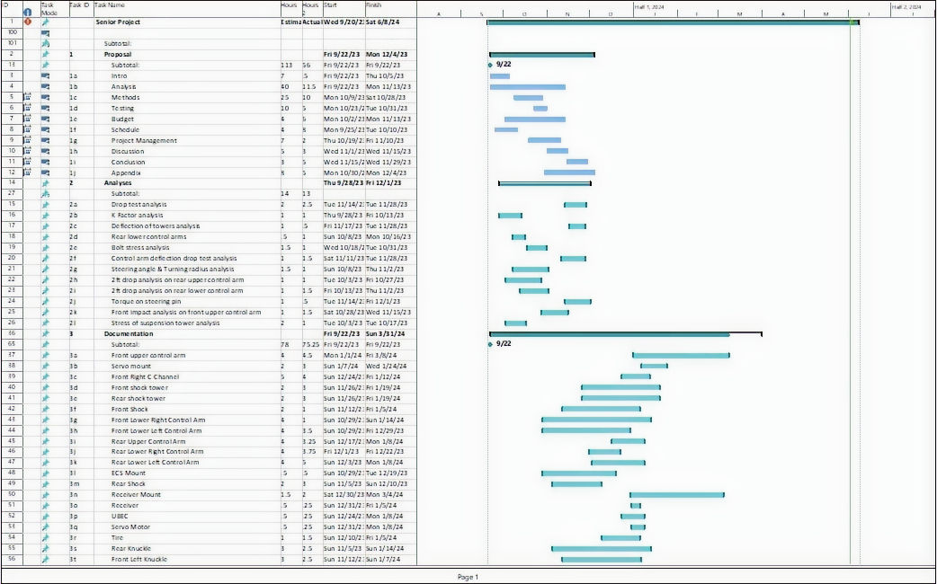
Figure S1- Gantt chart.
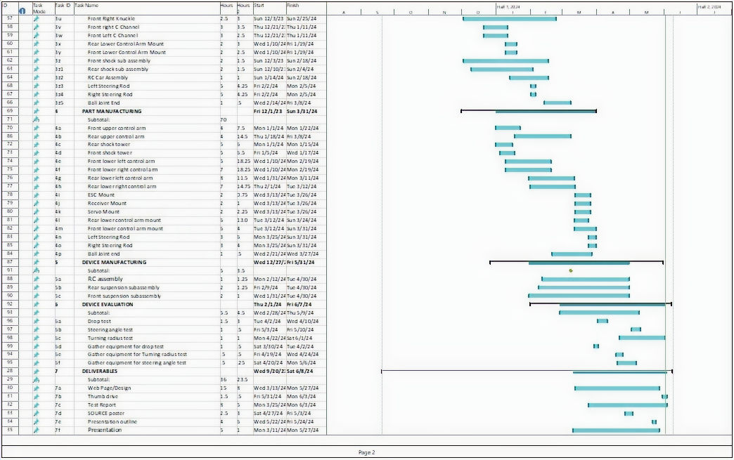
Figure S2- Gantt Chart continued.
Winter Updates:
The RC has underwent significant changes since Fall quarter. The control arms were the parts that changed the most on the RC. All of the RC components are almost ready for assembly. The only things left are to manufacture a drive shaft that will power the rear wheel axles and to wire up the electrical components. Additional changes have been made to improve clearance. The lower control arms were flipped upside down and swapped from the left to the right and vice versa for the lower right control arm. This raised the height to 0.93in. This was only done to see if the RC would have an immediate change in height. Slight modifications to the front lower control arms was necessary to fit the shock in place. This was done by melting the PLA+. Further efforts will be made to improve the height as it will benefit the RC in using the big wheels to crawl over obstacles.
New LCAs were manufactured and installed giving the RC a ground clearance of 1.5". The RC has a greater ground clearance, but the team is considering mimicking the front shock to the rear to allow drivability upside down in the case the RC ever flips over. The Rear LCAs could then be redesigned again if the rear shock tower is remodeled. The steering rods were redesigned to accept ball joint ends so that it is adjustable and does not add unwanted load on the rods. The hardware was fixed in place using JBWeld plastic bond and let to cure for an hour.
Actual time values are much higher than predicted because multiple parts had to be remanufactured for the same part due to breaking or failed prints.
Spring Updates:
During Spring, the team acquired equipment for testing of the RC device. The team gathered equipment that was already in possession of either CWU or the team. The weight scale was used to measure the weight of the RC and used as an assumption to calculate the deflection results. The first test was conducted on 4/2/2024 to measure maximum deflection of the entire RC from a 2ft drop. The testing took about 3 hours to complete, from arrival to Hogue Hall to cleaning up after testing. This test took longer than the rest because the RC had its 3D printed ball joint ends replaced for aluminum ones for greater tensile strength in the threads. The next test was conducted on the turning radius of the RC. The team gathered the materials that were already in the team's possession besides the purchase of a protractor. The RC device and controller is made sure to be charged before the testing of the RC to eliminate any risks. The RC was tested on 4/22/24 from 10:00AM to 11:00PM in the Fluke lab inside of Hogue Hall. The test took about an hour to complete. The final test was done on the RC's turning angle. This test was conducted on 5/6/24 from 10:00AM to 10:30PM in the Fluke lab inside of Hogue Hall. The RC was made sure to properly work before testing, which meant the RC and controller had to be fully charged to perform the test. The team gathered the equipment necessary which was the same as the previous materials list, but excluding the measuring tape. This test took about 30 minutes to perform
BUDGET
This RC project will be supervised to not be interrupted or exceed budget. The risk of any delay or fall back can be managed by planning out the schedule and including extra time in the schedule for any uncertainties. If following through with this can be done, risks of falling behind can be brought to a minimum and stay on schedule. In addition, taking note of the costs of every component bought can help keep track of the total amount of money spent on the project so far. Constantly keeping this value updated for every purchase made will help manage how much will be spent and reduce the amount of updates. Most components that can be easily manufactured will be 3D printed with PLA+ to reduce costs. Although parts will be 3D printed, the cost of 3D printing will be estimated using this equation: [(The cost of the filament) * (weight of the print in grams)]/1000. Much more costly components such as adapters and drive train components have been added to the budget. In addition to this new axles were needed to fit the knuckles, which meant the budget would increase. Smaller components such as fasteners also are accounted for in the budget.
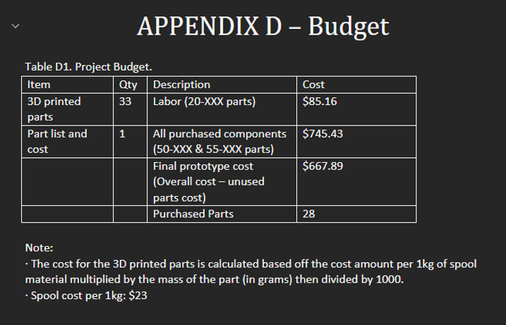
Figure F2- Budget list.
Winter Notes:
The initially purchased ESC, UBEC, Receiver, and Transmitter were not used in the latest prototype because the ESC, Receiver were burnt out while testing. To avoid waiting a month for a new receiver that matches the transmitter, a new receiver and transmitter were ordered quickly along with a more capable ESC. The more powerful ESC had an onboard system that serves the same purpose as the UBEC, which eliminated the use of the UBEC. These components are still included in the budget because they were used. For that reason the budget has surpassed the estimated amount of 500. A new ESC was purchased because the last ESC burned out like the first, but this time the receiver survived.
Spring Notes:
The newest 90A ESC and initially purchased motor were kept on the RC because the new brushless motor that was meant to run cooler would struggle to spin the wheels of the RC from a complete stop. The team used what they could without further exceeding the budget that was first set. If the team had more experience and knowledge with electrical components, the RC would have been improved from its current state. The budget in that case would be much lower and closer to the actual budget of 500 dollars. With the information the team now knows, the RC could have improved if the purchased motor was a brushless instead of a brushed motor because it would run more efficient and much cooler. The budget was further exceeded with the addition of a new ESC and brushless motor. The RC budget for the entire project has exceeded well over the cap that was set by the team, but not all parts purchased were used on the final prototype because during the construction and testing of the RC, the team discovered brushless motors were superior to brushed motors in this application. The purchase of a new brushless motor and a brushless ESC brought the budget much higher and up to 667.89 dollars. The total spent on the project is 830.59 dollars.
bottom of page